|
|
| |
 Directory of Listed
Products Directory of Listed
Products
|
|
| |


|
|
| |
BUILDING PRODUCTS LISTING PROGRAM |
|
| |
Class: |
Membrane Penetration |
|
| |
|
|
|
| |
Customer: |
Construction
Solutions, LLC |
|
| |
Location: |
7801 E. Gray Rd.,
Suite 110, Scottsdale, AZ,
85260 |
|
| |
|
|
|
|
Listing No.: |
B1072-1 |
|
| |
Effective Date: |
December 23, 2014 |
|
|
Last Revised: |
No Revisions to Date |
|
| |
Expires: |
N/A |
|
| |
|
|
|
|
Products: |
Construction Solutions
4 in. and 6 in. Metal Dryer Vent Box with Snap on Trim Ring |
|
|
|
|
|
| |
Standard(s): |
ASTM E814 “Standard Test Method for Fire Tests of Penetration
Firestop Systems”.
CAN/ULC S115 “Standard Method of Fire Tests of
Firestop Systems”. |
|
| |
|
|
|
| |
Label: |
4 in. dryer vent box is marked by Construction Solutions, LLC with
the following information: Construction Solutions’ 4 in. dryer vent
box trade name, QAI listing no. B1072-1A,
QAI logo with the ‘US’ and ‘C’ identifier, Ratings of 1-hour F,
1-hour T, and 1-hour H (CAN/ULC S115 only).
6 in. dryer vent box is
marked by Construction Solutions, LLC with the following
information: Construction Solutions’ 6 in. dryer vent box trade
name, QAI listing no. B1072-1B, QAI logo with the ‘US’ and ‘C’
identifier, Ratings of 41-minutes F, 41-minutes T, and 41-minutes H
(CAN/ULC S115 only). |
|
| |
|
|
|
|
Ratings: |
The following outlines the assembly and ratings of Construction
Solutions 4 in. and 6 in. dryer vent box:
|
Assembly
|
Test Standard
|
F-Rating
|
T-Rating
|
H-Rating
|
|
4 in. Dryer Vent Box
|
ASTM E814
|
1-hour
|
1-hour
|
N/A
|
|
CAN/ULC S115
|
1-hour
|
1-hour
|
1-hour
|
|
6 in. Dryer Vent Box
|
ASTM E814
|
41-minutes
|
41-minutes
|
N/A
|
|
CAN/ULC S115
|
41-minutes
|
41-minutes
|
41-minutes
|
Note: ASTM E814 does not use H-Rating to identify that the assembly
passed the hose stream test.
The hose stream test is a requirement to achieve an F-Rating.
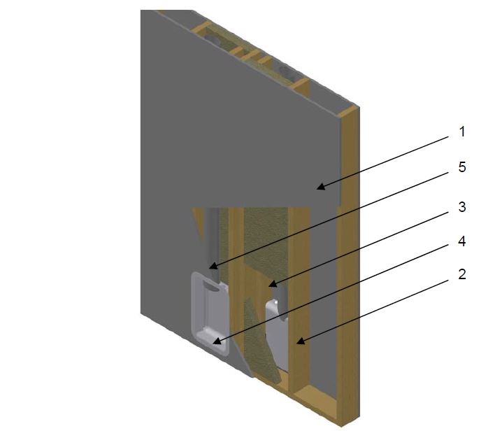
QAI Listing B1072-1A
ASTM E814 and CAN/ULC S115 – 1-Hour F Rating, 1-Hour T Rating, and 1-Hour H Rating (CAN/ULC S115 only) Non-load Bearing Wall Assembly
|
No.
|
COMPONENT
|
DESCRIPTION
|
|
1
|
Gypsum Board
|
Type:
|
Type X gypsum wallboard complying with ASTM C1396 and labeled by an approved agency
|
|
Thickness:
|
Single layer of 5/8 in. (16 mm) on each face of the wall
|
|
Application:
|
Sheathing is to be fastened to studs with #6 x 1-5/8 in. (41 mm) long coarse thread drywall screws spaced at 8 in. on center. Joints to
be taped and mudded, and fastener heads to be mudded.
|
|
2
|
Wall Studs
|
Stud Type:
|
Minimum nominal 2 x 6 in. (50 x 152 mm) Wood
|
|
Stud Spaced
|
Maximum 16 in. (406 mm) on center
|
|
3
|
Insulation
|
Type:
|
Mineral wool thermal insulation in compliance with ASTM C553 Type VII
|
|
Minimum Thickness:
|
2 inch (50 mm)
|
|
Nominal Density:
|
Minimum 4.0 lb/ft3 (64 kg/m3)
|
|
4
|
Dryer Box
|
Certified Manufacturer:
|
Construction Solutions
|
|
Certified Product:
|
Nominal 4 in. Construction Solutions Dryer Vent Box Kit
|
|
Box Dimensions:
|
10 in. (254 mm) wide by 17 in. (432 mm) high by 3-1/2 in. (89 mm) deep with a 1-1/4 in. (32 mm) flange. A 3 x 5 in. (76 x 127 mm) oval
cut out for the dryer vent on the top and 1-1/8 in. (29 mm) knockouts on the top and bottom for gas hook up. The box is formed from 22
gauge galvanized steel.
|
|
Trim Ring Dimensions:
|
9-7/8 in. (251 mm) wide by 16-7/8 in. (429 mm) high by 1-5/8 in. (41 mm) deep with a 1-5/16 in. (33 mm) flange. The trim ring is made
from 25 gauge galvanized steel.
|
|
Caulking:
|
PFP 4800DW
|
|
Installation:
|
A nominal 2 x 4 in. (50 x 100 mm) stud is installed into the stud cavity 10-3/4 in. (273 mm) from a 2 x 6 in. (50 x 152 mm) stud. The
dryer vent box was fastened to the 2 x 4 in. (50 x 100 mm) and 2 x 6 in. (50 x 152 mm) studs through three holes on each side of the
box using #8 x 1-1/2 in. (38 mm) wood screws. The galvanized steel dryer vent is inserted through the top of the box then caulked at
the vent/box interface. The opening cut into the gypsum board shall be a maximum of 10-1/2 in. (267 mm) wide by 17-1/2 in. (445 mm)
high. Only one box is permitted per stud cavity.
|
|
5
|
Vent Pipe
|
Size:
|
4 in. (101 mm) Round
|
|
Type:
|
26 gauge galvanized steel
|
QAI Listing B1072-1B
ASTM E814 and CAN/ULC S115 – 41-minutes F Rating, 41-minutes T Rating, and 41-minutes H Rating (CAN/ULC S115 only) Non-load Bearing Wall Assembly
|
No.
|
COMPONENT
|
DESCRIPTION
|
|
1
|
Gypsum Board
|
Type:
|
Type X gypsum wallboard complying with ASTM C1396 and labeled by an approved agency
|
|
Thickness:
|
Single layer of 5/8 in. (16 mm) on each face of the wall
|
|
Application:
|
Sheathing is to be fastened to studs with #6 x 1-5/8 in. (41 mm) long coarse thread drywall screws spaced at 8 in. on center. Joints to
be taped and mudded, and fastener heads to be mudded.
|
|
2
|
Wall Studs
|
Stud Type:
|
Minimum nominal 2 x 6 in. (50 x 152 mm) Wood
|
|
Stud Spaced
|
Maximum 16 in. (406 mm) on center
|
|
3
|
Cavity Insulation
|
Type:
|
Mineral wool thermal insulation in compliance with ASTM C553 Type VII
|
|
Minimum Thickness:
|
2 inch (50 mm)
|
|
Nominal Density:
|
Nominal Density:
|
|
Insulation Behind the Dryer Vent Box
|
Type:
|
Mineral wool thermal insulation in compliance with ASTM C612 Type IVA
|
|
Dimensions:
|
10 in. (254 mm) x 17 in. (432 mm) x 1 in. (25 mm) thick directly behind the box
|
|
Nominal Density:
|
3.5 lb/ft3 (56 kg/m3)
|
|
Install:
|
A 10 in. by 17 in. area shall be cut from the 2 in. cavity insulation in the area behind the Dryer Vent Box, a 10 in. by 17 in. piece
of 1 in. insulation shall then be placed in the cut out.
|
|
4
|
Dryer Vent Box
|
Certified Product:
|
Nominal 6 in. Construction Solutions Dryer Vent Box Kit
|
|
Box Dimensions:
|
10 in. (254 mm) wide by 17 in. (432 mm) high by 5 in. (127 mm) deep with a 1-1/4 in. (32 mm) flange. A 4-3/16 in. (106 mm) circular cut
out for the dryer vent on the top and 1-1/8 in. (29 mm) knockouts on the top and bottom for gas hook up. The box is formed from 22
gauge galvanized steel.
|
|
Trim Ring Dimensions:
|
9-7/8 in. (251 mm) wide by 16-7/8 in. (429 mm) high by 1-5/8 in. (41 mm) deep with a 1-5/16 in. (33 mm) flange. The trim ring is made
from 25 gauge galvanized steel.
|
|
Caulking:
|
PFP 4800DW
|
|
Installation:
|
A nominal 2 x 4 in. (50 x 100 mm) stud is installed into the stud cavity 10-3/4 in. (273 mm) from a 2 x 6 in. (50 x 152 mm) stud. The
dryer vent box was fastened to the 2 x 4 in. (50 x 100 mm) and 2 x 6 in. (50 x 152 mm) studs through three holes on each side of the
box using #8 x 1-1/2 in. (38 mm) wood screws. The galvanized steel dryer vent is inserted through the top of the box then caulked at
the vent/box interface. The opening cut into the gypsum board shall be a maximum of 10-1/2 in. (267 mm) wide by 17-1/2 in. (445 mm)
high. Only one box is permitted per stud cavity.
|
|
5
|
Vent Pipe
|
Size:
|
4 in. (101 mm) Round
|
|
Type:
|
26 gauge galvanized steel
|
|
|
| |
|
|
|
| |
Note: |
|
|
|
|
| |
|
|
| |
The materials, products or systems listed in this directory have
been qualified to bear the QAI Listing Mark under the conditions
stated with each Listing. Only those products bearing the QAI
Listing Mark are considered to be listed by QAI.
No warrantee
is expressed or implied, and no guarantee is provided that any
jurisdictional authority will accept the Listing found herein. The
appropriate authorities should be contacted regarding the
acceptability of any given Listing.
Visit the QAI Online
Listing Directory located at www.qai.org for
the most up to date version of this Listing and to validate that
this QAI Listing is active.
Questions regarding this listing
may be directed to info@qai.org.
Please include the listing number in the request.
|
|
| |
Copyright QAI Laboratories, 2015 |
|